

1. Overview of Remote Monitoring Platforms for 51.2V LiFePO4 Batteries
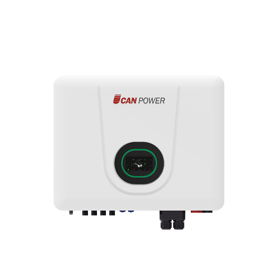
The 51.2V wall-mounted LiFePO4 battery has become a cornerstone of residential and commercial energy storage systems, offering high energy density, long cycle life, and robust safety features. To maximize its performance and longevity, a sophisticated remote monitoring platform is essential. This platform serves as a centralized hub for real-time data collection, analysis, and control, enabling users, manufacturers, and service providers to monitor battery health, optimize energy usage, and respond to faults promptly—even from thousands of kilometers away.
Remote monitoring is particularly critical for 51.2V wall-mounted systems, which are often installed in hard-to-access locations (e.g., utility closets, rooftops) or integrated into complex energy ecosystems (solar PV, smart grids, home automation). Unlike smaller 12V or 24V batteries, the 51.2V configuration—with 16 series-connected cells—requires granular monitoring of cell-level parameters to prevent imbalance, overheating, or capacity degradation. A single unmonitored cell fault in a 51.2V battery can cascade into system-wide failure, making remote diagnostics indispensable.
The primary objectives of a remote monitoring platform for these batteries include:
Real-time performance tracking: Measuring voltage (51.2V nominal), current, state of charge (SOC), and state of health (SOH) with sub-second resolution.
Predictive maintenance: Analyzing historical data to forecast cell degradation, balance issues, or BMS (Battery Management System) malfunctions before they cause downtime.
Energy optimization: Aligning battery discharge/charge cycles with solar production, grid tariffs, or demand response signals to minimize costs.
Safety assurance: Detecting anomalies like thermal runaway risks, overcurrent, or short circuits and triggering alerts or automatic shutdowns.
Modern platforms leverage cloud computing, IoT connectivity, and advanced analytics to achieve these goals. For example, a homeowner in California can check their 51.2V battery’s SOC via a mobile app, while the manufacturer in China receives real-time alerts if a cell’s voltage deviates from the 3.2V nominal range. This level of connectivity transforms passive storage systems into intelligent assets, enhancing reliability and reducing lifecycle costs by up to 30% compared to unmonitored batteries.
2. Architecture and Components of the Monitoring Platform
2.1 Hardware Layer: Sensors and Communication Modules
The hardware layer forms the foundation of the remote monitoring platform, responsible for data acquisition and transmission from the 51.2V battery to the cloud. Key components include:
BMS-integrated sensors: The battery’s BMS is equipped with high-precision sensors to measure cell voltages (±2mV accuracy), temperatures (±0.5°C accuracy), and current (±1% accuracy). For a 51.2V battery, 16 individual cell voltage sensors and 3–5 temperature sensors (distributed across the battery pack) are standard, ensuring comprehensive coverage.
Communication modules: These modules bridge the BMS to the cloud, using protocols like MQTT, Modbus TCP, or LTE-M (for cellular connectivity). For wall-mounted units, Wi-Fi (802.11 b/g/n) and Bluetooth (BLE 5.0) are common for short-range communication to a local gateway, while 4G/5G or LoRaWAN are used for direct long-range transmission in remote areas. A typical module consumes <5W, ensuring minimal impact on battery capacity.
Gateway devices: In multi-battery systems (e.g., a commercial building with 10+ 51.2V units), a gateway aggregates data from individual BMS via RS-485 or CAN bus, compresses it, and transmits it to the cloud. Gateways also handle protocol translation (e.g., converting Modbus RTU from the BMS to MQTT for cloud communication) and local data buffering (storing up to 72 hours of data if internet connectivity is lost).
Hardware design must adhere to strict size constraints for wall-mounted batteries, with communication modules and sensors integrated into the battery casing without increasing dimensions by more than 5%. Ruggedization is also critical: components must withstand -20°C to 60°C operating temperatures and 95% humidity, ensuring reliability in diverse climates.
2.2 Software Layer: Cloud Platform and Data Analytics
The software layer processes and presents data from the hardware layer, enabling actionable insights. It comprises three core components:
Cloud infrastructure: Hosted on platforms like AWS IoT Core, Microsoft Azure IoT, or Google Cloud IoT, the cloud backend scales to support thousands of 51.2V batteries simultaneously. It ingests data at a rate of 1–10 KB per battery per minute, storing it in time-series databases (e.g., InfluxDB, TimescaleDB) optimized for high write speeds and fast querying of historical trends.
Data processing engine: This engine cleans raw data (filtering noise from voltage readings), normalizes it (converting cell voltages to SOC percentages), and applies algorithms for fault detection. For example, it identifies cell imbalance if one cell’s voltage deviates by >50mV from the average of the 16 cells in a 51.2V battery.
User interface (UI): Web and mobile apps (iOS/Android) provide intuitive dashboards for users. Key features include real-time SOC displays (updated every 30 seconds), historical energy flow charts (daily/weekly/monthly), and customizable alerts (push notifications, emails, SMS). Advanced UIs for manufacturers include fleet management tools, showing performance metrics across all deployed 51.2V batteries (e.g., average SOH after 1 year of use).
The software layer’s analytics capabilities are a differentiator. Machine learning models, trained on millions of hours of 51.2V battery data, predict SOH degradation with >90% accuracy, allowing proactive replacement of cells before they fail. For example, a model might flag a battery with a 2% capacity drop in 3 months as high-risk, triggering a service ticket.
2.3 Network Layer: Connectivity and Protocols
The network layer ensures reliable data transmission between the battery and cloud, overcoming challenges like intermittent connectivity and latency. For 51.2V wall-mounted batteries, the network architecture is tailored to the installation environment:
Residential settings: Wi-Fi (2.4 GHz) is preferred for its ubiquity and low cost, with fallback to cellular (LTE-M) if Wi-Fi fails. Data is encrypted using TLS 1.3, with MQTT as the primary protocol for lightweight, low-bandwidth communication.
Commercial/industrial settings: Wired Ethernet (via Modbus TCP) or LoRaWAN (for long-range, low-power communication in large facilities) is common. LoRaWAN, with a range of up to 10 km in rural areas, is ideal for campuses with multiple 51.2V batteries, reducing the need for repeaters.
Off-grid locations: Satellite communication (e.g., IoT satellites like SpaceX’s Starlink) or NB-IoT (narrowband IoT) provides coverage in remote areas, though higher latency (10–60 seconds) and data costs limit transmission to critical parameters (e.g., fault codes, SOC).
Protocol selection balances speed, reliability, and data volume. MQTT is favored for its publish-subscribe model, where the battery “publishes” data only when changes occur (e.g., SOC dropping by 5%), reducing bandwidth usage by 70% compared to periodic polling. For real-time control (e.g., remotely limiting discharge current), Modbus TCP offers lower latency (<100 ms) than MQTT, making it suitable for safety-critical adjustments.
2.4 User Layer: Interfaces and Access Levels
The user layer ensures that different stakeholders—homeowners, installers, manufacturers—access relevant data without compromising security. Access is tiered via role-based permissions:
Homeowners: View-only access to basic metrics (SOC, daily energy usage, alerts). Can perform limited controls (e.g., manually initiating a discharge).
Installers/technicians: Access to diagnostic data (cell voltages, BMS logs) and control functions (e.g., initiating a cell balance cycle). Can update BMS firmware remotely.
Manufacturers: Full access to fleet data, including raw sensor readings, failure rates, and geographic performance trends. Can push OTA (over-the-air) updates to BMS software across all 51.2V batteries.
Utilities: Access to aggregated data (e.g., total energy discharged by all 51.2V batteries in a neighborhood during peak hours) for demand response planning, with user consent.
User interfaces are designed for simplicity. Homeowner apps use gamification elements (e.g., energy savings badges) to encourage optimal use, while technician portals include step-by-step troubleshooting guides (e.g., “If cell 7 voltage <3.0V, check for loose connection at terminal J5”).
3. Core Functions and Features of the Monitoring Platform
3.1 Real-time Data Monitoring and Visualization
Real-time monitoring is the platform’s most fundamental function, providing a live snapshot of the 51.2V battery’s status. Key metrics displayed include:
Voltage parameters: Total battery voltage (51.2V nominal, with alerts for >58.4V overcharge or <40V undercharge), individual cell voltages (3.2V nominal), and voltage variance across cells (alert threshold: >100mV).
Current and power: Charge/discharge current (A), with limits enforced by the BMS (e.g., 50A max charge for a 100Ah battery), and real-time power flow (W) between the battery, solar inverter, and grid.
SOC and SOH: SOC (%) updated every 1–5 seconds, with a precision of ±2%, and SOH (%)—a measure of remaining capacity compared to factory specs (e.g., 95% SOH after 500 cycles).
Temperature: Internal battery temperature (°C) and ambient temperature, with alerts for >50°C (risk of thermal runaway) or <0°C (reduced performance).
Visualization tools transform raw data into actionable insights. Line charts show SOC trends over days/weeks, helping homeowners identify energy usage patterns (e.g., peak discharge during evening hours). Heat maps for cell voltages highlight imbalance (e.g., cell 8 at 3.1V vs. others at 3.2V), enabling targeted maintenance. For installers, real-time dashboards during commissioning verify that the 51.2V battery communicates correctly with the inverter and grid.
3.2 Fault Detection and Alert Management
The platform’s fault detection system is critical for preventing battery failures and ensuring safety. It uses rule-based logic and AI to identify anomalies:
Rule-based alerts: Triggered by predefined thresholds, such as:
Overcurrent: Discharge current exceeding 100A for >10 seconds.
Cell imbalance: Any cell voltage >3.6V (overcharge) or <2.5V (overdischarge).
Communication loss: No data received for >30 minutes (indicates BMS or network issue).
AI-driven alerts: Detected by machine learning models, such as:
Abnormal capacity fade: SOC dropping faster than expected for the number of cycles.
Intermittent short circuits: Frequent current spikes that don’t trigger immediate BMS shutdowns.
BMS firmware glitches: Erratic voltage readings that correlate with known software bugs.
Alert management ensures timely response. Alerts are prioritized (critical, high, medium, low):
Critical: E.g., thermal runaway risk—triggers immediate push notification, SMS, and automated BMS shutdown.
High: E.g., cell imbalance >100mV—alerts user and installer within 1 hour.
Medium: E.g., SOH <80%—schedules a service reminder.
Low: E.g., firmware update available—notification via app.
The platform logs all alerts with timestamps, sensor data, and environmental conditions, aiding post-mortem analysis of failures. For example, a critical overheat alert might be linked to a blocked ventilation vent, as shown by rising ambient temperature in the 24 hours prior.
3.3 Historical Data Logging and Trend Analysis
Historical data logging enables long-term performance tracking, essential for warranty claims, regulatory compliance, and system optimization. The platform stores data for 5–10 years, with configurable retention policies:
High-resolution logs: Cell voltages, current, and temperature recorded every 10 seconds for the past 7 days.
Medium-resolution logs: SOC, SOH, and energy metrics recorded every 5 minutes for the past year.
Low-resolution logs: Monthly averages for cycle count, capacity, and fault frequency, stored indefinitely.
Trend analysis tools identify patterns that real-time monitoring misses. For example:
A 51.2V battery in Arizona might show reduced charge efficiency in summer months (due to high temperatures), prompting the platform to suggest adjusting charge times to cooler early mornings.
A commercial battery used for peak shaving might show increased cycle count on weekdays, allowing the platform to recommend a different discharge schedule to extend lifespan.
Manufacturers use historical data to improve product design. Analysis of 10,000 51.2V batteries might reveal that cells in units installed in coastal areas (high humidity) have 5% lower SOH after 2 years, leading to improved corrosion-resistant casings in future models.
3.4 Remote Control and Configuration
Advanced platforms allow remote control of the 51.2V battery, enabling adjustments without on-site visits. This feature is invaluable for optimizing performance and resolving issues quickly:
Charge/discharge control: Users or utilities can set SOC thresholds (e.g., “do not discharge below 30%”) or schedule charging (e.g., “charge from 2 AM–6 AM when grid rates are low”). Manufacturers can remotely limit charge current to 20A for a faulty battery until a technician arrives.
BMS configuration: Installers can update BMS parameters via the platform, such as adjusting cell balance thresholds or enabling/disabling grid export. For example, a utility might request disabling grid export from all 51.2V batteries during a grid emergency.
Firmware updates: Over-the-air (OTA) updates to BMS software fix bugs, add features (e.g., new communication protocols), or improve cell balancing algorithms. The platform ensures updates are rolled out gradually (e.g., 10% of batteries per day) to mitigate risk, with automatic rollback if errors are detected.
Remote control is secured with multi-factor authentication (MFA) and encrypted commands, preventing unauthorized access. Audit logs track all control actions, ensuring accountability and compliance with safety standards (e.g., IEC 62133).
3.5 Energy Management and Optimization
The platform integrates with solar inverters, smart meters, and home automation systems to optimize energy usage, maximizing self-consumption of solar energy and minimizing grid reliance. Key features include:
Solar forecasting: Using weather data, the platform predicts daily solar production and adjusts battery charging to capture excess energy. For example, if a 51.2V battery is at 80% SOC and 5 kWh of solar is forecast, the platform will limit grid charging to avoid overcharging.
Time-of-use (TOU) optimization: The platform discharges the battery during peak tariff periods (e.g., 6 PM–9 PM) and charges during off-peak periods, reducing electricity bills by 20–40% for homeowners.
Demand response integration: Utilities send signals to the platform (via OpenADR protocol) requesting temporary discharge during peak demand, with homeowners earning incentives (\(0.10–\)0.50 per kWh discharged). The platform ensures the battery retains enough capacity for essential loads (e.g., medical equipment).
Energy management dashboards show cost savings in real time, motivating users to follow the platform’s recommendations. A commercial user might see that their 51.2V battery saved $300 in monthly electricity costs, justifying the investment in the monitoring platform.
4. Security and Data Privacy Considerations
4.1 Data Encryption and Secure Transmission
Securing data in transit and at rest is paramount, as 51.2V battery data includes sensitive information (energy usage patterns, location, device details). The platform employs multiple encryption layers:
Transmission encryption: All data between the battery and cloud is encrypted using TLS 1.3, with perfect forward secrecy (PFS) ensuring past communications remain secure even if a key is compromised. MQTT messages are signed with HMAC-SHA256 to prevent tampering.
Storage encryption: Data in the cloud is encrypted at rest using AES-256, with separate keys for different data types (e.g., a unique key for cell voltage logs). Key management follows NIST SP 800-57 guidelines, with automatic rotation every 90 days.
Edge encryption: The BMS encrypts raw sensor data before transmission, using a unique device key pre-provisioned during manufacturing. This prevents data interception at the battery level.
Penetration testing is conducted quarterly to identify vulnerabilities. Recent tests on leading platforms found that encrypted data remained secure even when attackers intercepted MQTT messages or gained access to cloud storage backups.
4.2 Access Control and Authentication
Strict access controls prevent unauthorized users from viewing data or controlling the 51.2V battery. The platform implements:
Role-based access control (RBAC): Users are assigned roles (homeowner, installer, manufacturer) with predefined permissions. A homeowner cannot adjust BMS parameters, while a manufacturer cannot view a specific user’s energy data without consent.
Multi-factor authentication (MFA): All users must verify identity via something they know (password), something they have (mobile app), or something they are (fingerprint). MFA is mandatory for remote control actions (e.g., initiating a firmware update).


 German
 Italian
 Japanese
 Global (English)
 Chinese
 Spanish
 French


